
byDavid KohanbashonMay 31, 2023
In this post, we will be discussing the Hands on Robot Design series, focusing on the drone’s sensors and computer systems. The payload was built with weight minimization in mind, making it an efficient and effective system. In this article, we will explore the various sensors and computer components used in the drone’s payload and how they work together to enable the drone to perform its tasks.
This post is part of the Hands on Robot Design series. See here for the full list of posts/topics for information on mechanical, electrical, motion control, computing, sensors, and more.
The Payload and Sensors
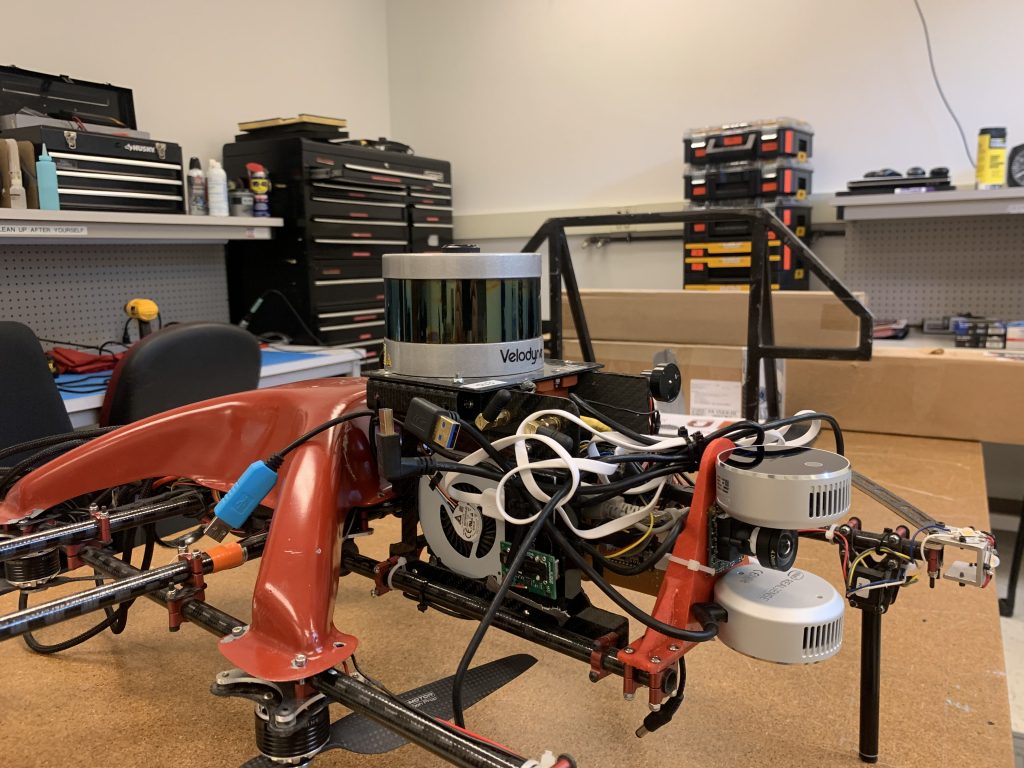
Once we had a drone, we needed the sensors and computer to make this drone operate. Keeping with the idea of trying to make the drone as light as possible (and not caring about aesthetic) the payload was built with weight minimization in mind. The payload was mounted to the carbon fiber tubes near the front of the drone. On the two vertical sidewalls, one of the side walls was dedicated to the power electronics and the other side wall was dedicated to the computer.
The computer ran all of the autonomy and control software for the drone as well as the object detection. To assist with object detection, an Intel compute stick was also used. The main computer was an Intel NUC i7.
Payload Sensor Specification:
Velodyne (VLP-16) Puck Lite
Xsens MTi-200-VRU-2A8G4 IMU
Intel Realsense L515 (x2)
UEye UI-3241LE-M/C RGB Cam
CozIR®-LP3 1% CO2 Sensor
Intel Dual Band Wireless-Ac 8265 W/Bt WiFi (For WiFi and Bluetooth device detection)
Mappings and Localizations
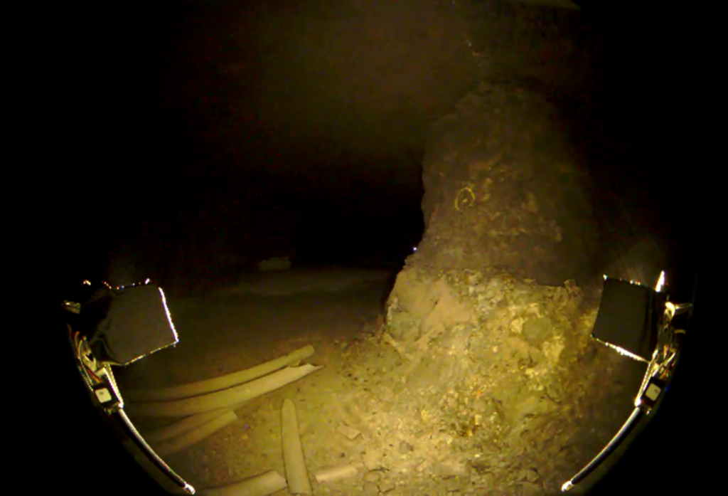
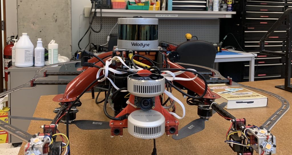
For exploration mapping and localization (SLAM) the Velodyne VLP16 Puck Lite LIDAR was the primary sensor. Realsense L515’s RGBD cameras were used both for helping with vertical localization (these were particularly useful for ascending/descending in vertical shafts) and object detection. The uEye visual camera (mounted between the Realsense cameras) with a fish eye lens was the primary sensor used for object detection to find the required artifacts in the subterranean environments.
Additional Sensors and Components
In addition to the Velodyne LIDAR and Realsense cameras, the drone also had an Xsens IMU (small orange box) mounted rigidly directly below the Velodyne (upside down).
Frequently Asked Questions
Question 1: What type of sensors did you use in the drone’s payload?
The drone’s payload used a combination of sensors, including the Velodyne VLP16 Puck Lite LIDAR, Realsense L515’s RGBD cameras, uEye visual camera with a fish eye lens, and Xsens IMU.
Question 2: How did you implement the SLAM algorithm?
We used the Velodyne LIDAR as the primary sensor for SLAM, along with the Realsense cameras and uEye camera.
Question 3: What was the role of the Intel NUC i7 computer in the drone’s payload?
The Intel NUC i7 computer ran the autonomy and control software for the drone, as well as the object detection.
Question 4: How did you manage the power components in the drone’s payload?
The power components in the drone’s payload were managed through a dedicated power electronics board.
Question 5: What was the purpose of the Xsens IMU in the drone’s payload?
The Xsens IMU was used to provide inertial data to the drone’s autopilot system, allowing for more accurate and stable flight.
Conclusion
In conclusion, the drone’s payload was designed to be efficient and effective, using a combination of sensors and computer components to enable the drone to perform its tasks. The Velodyne LIDAR and Realsense cameras provided excellent mapping and localization capabilities, while the Xsens IMU and Intel NUC i7 computer provided precise inertial data and autonomy.
Liked it? Take a second to support David Kohanbash on Patreon!
Frequently Asked Questions
Main image source:
Liked it? Take a second to support David Kohanbash on Patreon!


